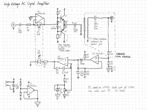
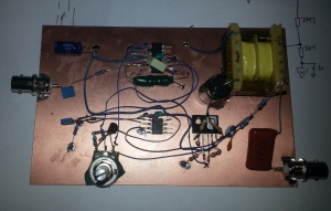
Here’s a quick one. This came from necessity more than anything, so it’s not great. This circuit amplifies a sine input (frequency and voltage range depends on transformer; I got 1kHz to 30 kHz; 14Vpp to 480Vpp/5Vrms to 170Vrms), for example, for testing and comparing AC voltmeters. Distortion is not great, but it served its purpose. It is built from common parts that are often lying around the lab, so I thought somebody might be interested.
R2 and D4 form a resistive optocoupler, also known as a Vactrol. Simply place a standard LED and photoresistor together, so that the LED illuminates the resistor, then seal them with tape and/or shrink tubing.
I used an LM393 to form the peak detector, rather than the fourth unit of the LM324. The LM324 may work fine for you – in fact, it may even work better – but I didn’t test that.
Input voltage range is from 12V to 30V. The maximum output voltage will increase as the input voltage increases, though the set point should be stabilized by U5 (TL431). You could use a Zener diode in place of the TL431.
Q1 and Q2 get warm, so make sure to “heat sink” them (possibly just by gluing them to the board; they don’t get very hot). Depending on the transformer used, you may be able to decrease their quiescent current by increasing R5 and R6.
High voltage is present on the output, so do not lick it.
The control loop is a bit finicky. Depending on the devices used in your Vactrol, you may need to adjust R11 or C6. If you want to decrease the frequency below 1 kHz, you may need to decrease R10; this will also affect the control loop.
I may do a PCB design for this at some point, if I can improve the performance a bit.

